Sunday, May 23, 1999

Ok, it has taken me a bit too long to get here. I aimed to begin working on this page about a week ago but I got sidetracked by an onery PPP daemon and didn't get to it. Also I have been wrangling with other software difficulties which have slowed me down some. But I am here now and in full force. =) Even though I have not been working on this page I have been working on learning the 3d API for java. I will run through where I am at currently, and where I hope to go.

A bit of history. This project was originally begun by Andy Trent, Lewis Baumstark, and Michael Sandt in the Fall of 1998 for CSc 420 (Programming Languages.) They developed a two dimensional robot simulator. At the end of that semester Andy came under the pay of the Manufacturing Center through the kind-hearted work of Dr. Ramaswamy. His work was also being conducted through the CSc 370 class. I got involved, as did Danyel Bruggink, through that class. It is now the summer following 370 and Andy, Danyel and I developed a 3D version of the original project. I worked primarily in the class on a parser to command the robot. I did next to nothing with java 3d. This summer my job is to further develop the project.

For the parsing aspect of the project I have a pretty good idea of what needs to be developed since I am the one who has done all of the work thus far. My primary goals are: The tougher part of the summer is going to be the work on the java 3d part of things. The information that I have here is only based on looking at how the simulator works right now and from what Andy has told me about his work. So there is obviously alot of work to be done on this project.
Monday, May 24, 1999 10:02 AM

I am one of those people who learns in part by explaining what I am learning to others. I am wanting to be a teacher, convenient, huh? =) What I am going to do for the next couple days is explain what I understand and don't understand of the java 3d API.

To begin, with the developers of the 3d API were very graphical people (as you might expect.) Much of the structure of the language is graph based and difficult to represent without drawing a picture. I have some drawings (well, I had some drawings but I left them in Bluff City) =) but I am going to redo them and scan them in and put them here.

I do not intend what I am going to be writing here to be a simple recapitulation of the
API or the API tutorial. But because those are my only sources of information other than the mailing list there is going to be by necessity alot of crossover.

First I will do a rundown of the basics of how this robot is laid out. We modeled a PUMA robot (Programmable Universal Machine for Assembly if my memory serves me correctly) roughly. Robotics research promises to revolutionize the production and eventually the service industries and there is quite a bit done around the world. A nice site for jumping off from is one at the University of Alberta. The work that we are doing now is very conceivable extensible into the realm of actual robotics control. Because the work to this point has been the creation of self-contained objects which have a fairly generic interface it would be possible to create interfaces for different controlling interfaces and reuse the code already developed.

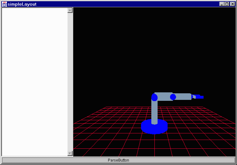
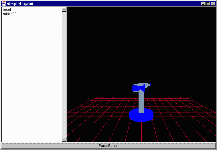
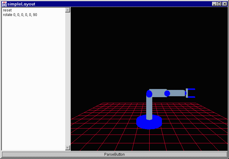
Our puma robot looks like this:

The basic robot

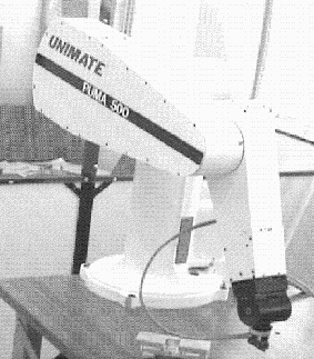
That is what the screen looks like when the program first loads. Pay attention to it because when I am explaining the joints they are each going to be rotated 90° from this initial state. It is really a bit different from what a real puma looks like:

A real puma

But it is certainly a good approximation and it is possible to develop a better one later. Java 3D supports loading of models developed in 3d graphics programs and there is a SGI Octane sitting in front of me. Surely we can work something out. ;)

A puma has 6 degrees of revolute freedom, that is to say that it rotates around 6 joints.

The first is the base. The robot can rotate parallel to the plane of the ground. I have to check the tolerances on how far this joint can rotate. I know that each joint has certain tolerances as to the extent that it can rotate and from reading Andy's code I am trying to figure out what these are.

Here is the code that I am looking at:
Joint0 = new Joint(tempM, new Vector3f(0f, .6604f, 0f));
Joint1 = new Joint(((float)(Math.PI / 2)), (-(float)(Math.PI / 2)), 0, 0, -160, 160 );
Joint2 = new Joint(0f, 0f, .432f, .1495f, -225, 45);
Joint3 = new Joint(((float)(Math.PI / 2)), ((float)(Math.PI / 2)), 0f, 0f, -45, 225);
Joint4 = new Joint(0f, (-(float)(Math.PI / 2)), 0f, .432f, -110, 170);
Joint5 = new Joint(0f, ((float)(Math.PI / 2)), 0f, 0f, -100, 100);
Joint6 = new Joint(0f, 0f, 0f, .0565f, -266, 266);
Joints 1 - 5 have an angle range at the end but not the first one. His explanation for the adapted constructor is this:

"This constructor is called by the 0th joint and puts it in the proper place to build the rest of the robot on top of it. This is necessary because in all the books, the robot just starts with joint1 being defined from a coordinate frame that does not match the standard x=horizontal, y=vertical etc model. I have to get the 0th frame in the correct orientation so that joint1 and all subsequent will be correctly represented."

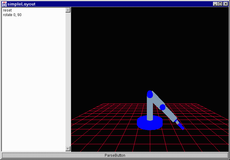
I don't really understand why that would leave out tolerances, but for the moment I will accept that I don't get it and I will fill them in later. Here is the robot after a 90° rotation about its base:

To answer my own question now that I pay attention; there are 7 joints and 6 degrees of freedom. The first joint then must be joint1 and joint0 is something else that I will figure out later. So joint one's tolerances are: -160° to 160° (delta = 360°).

Joint number 1

The next joint seems to have a tolerance of -225° to 45° (delta = 300°). It bends much like it looks like it would, perpendicular to the plane of the floor. It will only rotate 45° however because that takes it to the limit of its tolerance. You can see as well here the problem about it rotating through other things like the floor.

Joint number 2

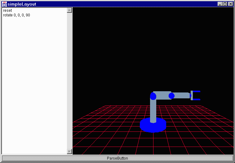
The next joint is much the same, having a tolerance of -45° to 225° (delta = 300°) and also rotating perpendicularly to the floor.

Joint number 3

The next joint is at the same point as the previous one but it rotates clockwise and adjusts the orientation of the hand changing but not changing its distance from the robot or the floor. This movement sparks a question. Its tolerances are -110° to 170° (delta = 280°).

Joint number 4

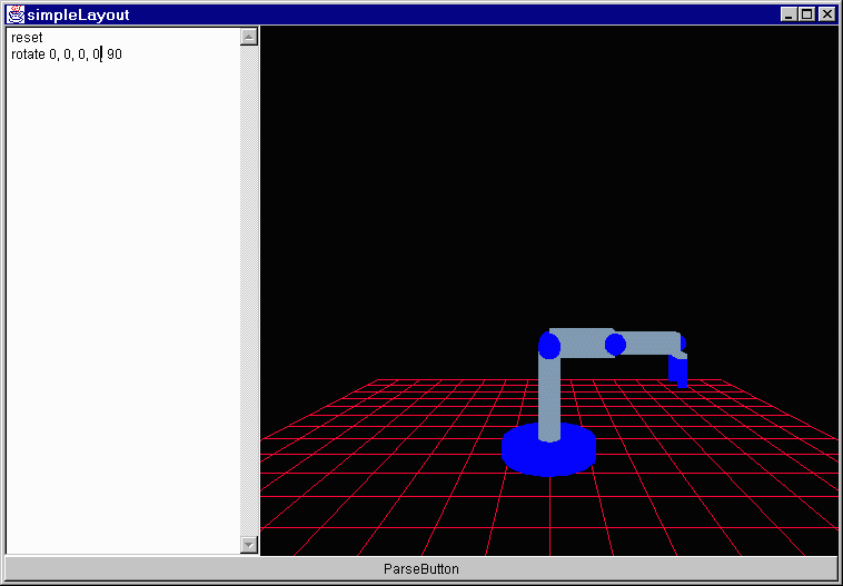
The next joint controls another aspect of the orientation of the hand. This is called the pitch of the hand and as you can see it is the angle between the arm and the plane of the hand. Its tolerances are 100° to 100°.

Joint number 5

Finally you have a joint which as best I can tell does exactly the same orientation change as joint 4. It controls rotation.

Joint number 6


I am having difficulty telling the difference between joint 4 and joint 6. It seems as though they both rotate along the same axis.

Nevermind I think. It is true that they both rotate along the same axis in a sense. They are both rotational joints and control the orientation of the plane of the hand to the rest of the robot but the fact that they have different bases changes the way that they change orientation. The example that I was looking at was this:

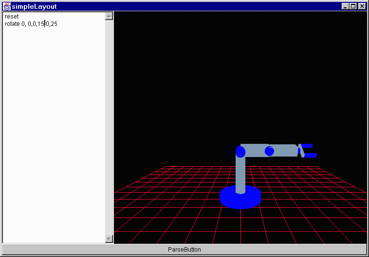
First rotate joint 4 15° and joint 6 25°:

Rotate <0, 0, 0, 15, 0, 25>

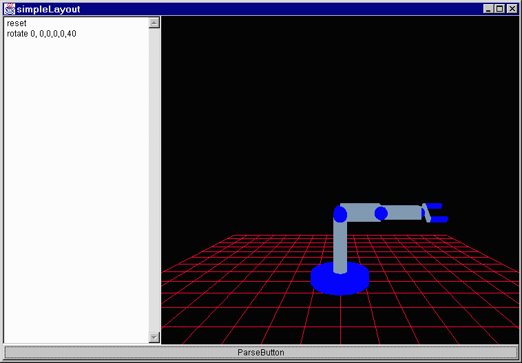
Those rotations produce the same result as rotating joint 6 40°:

Rotate <0, 0, 0, 0, 0, 40>

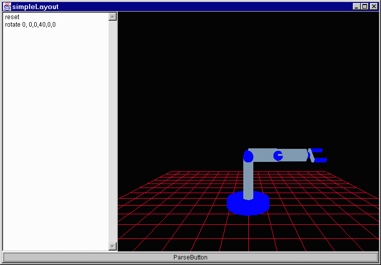
Or rotating joint 4 40°:

Rotate <0, 0, 0, 40, 0, 0>

The reason that this works is that there are no rotations along joints 3 or 5. If there were then there would be differences in the end orientation of the claw in relation to the robot.

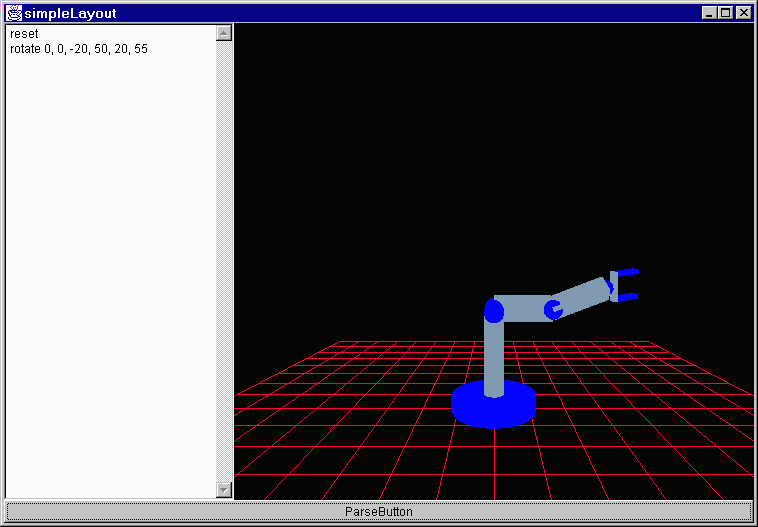
A rotation of <0°, 0°, -20°, 50°, 20°, 55°>:

Rotate <0, 0, -20, 50, 20, 55>

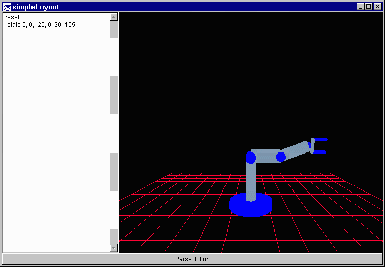
Is not the same as a rotation of <0°, 0°, -20°, 0°, 20°, 105°>:

Rotate <0, 0, -20, 0, 20, 105>

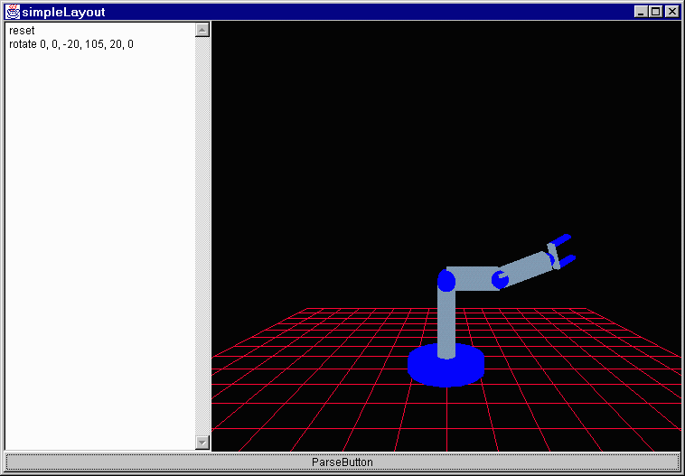
Or a rotation of <0°, 0°, -20°, 105°, 20°, 0°>:

Rotate <0, 0, -20, 105, 20, 0>

That, I think is it for today. I will maybe come back later and talk more about scene graphs and how this robot is described in java 3d.
Thursday, May 27, 1999 8:21 AM

News flash... Java 3d is hard to understand. This is my carefully prepared analysis after a day of mucking through the stuff. I am however going to start out simply and slowly explaining what I do understand.

To being with, the java 3d API is a set of java functions designed to help a java programmer design and implement three dimensional graphics. What I in specific am doing is working with a three dimensional simulation of a puma robotic arm.

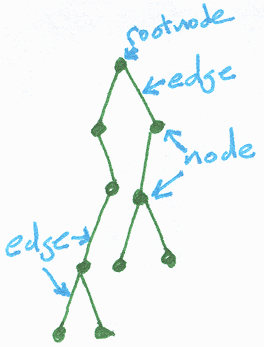
The abstract structure of a java 3d program is that of a tree or, as they call it, a directed acyclic graph. The basic concept is that you begin with a root and from that root branches "grow." The simplest trees are binary trees and each root can have at most two branches. Also each branch of a binary tree is itself a subtree to which all the same rules apply.

A simple binary tree would look like this perhaps:

Simple binary tree

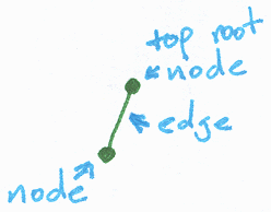
The only rules about how the tree is formed is that no root may have more than two branches and every root except for the top one must have one and only one parent. To introduce a couple of terms from graph theory (since a tree is a graph) the dots where the lines meet are called nodes and the lines connecting the nodes are called edges. The simplest tree is one which consists only of a single root node.

Simplest binary tree

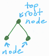
Makes sense? One step up from that would be one which consists of a root with a single branch. The node that is connected to the top root by an edge is known as a child of the root.

One branch binary tree

This being computer science and all there is no real up or down. The top root could very easily be drawn at the bottom of the graph or even in the middle but for the sake of simplicity and conformity it is drawn at the top. To add one more layer of complexity to our growing young tree, let's sprout it another branch.

Two branch binary tree

Because one of the rules for growing binary trees is that they are allowed only to have two branches, this is all of the branches that may grow out of this root. The tree may still continue to grow however because each of the children of the top root are themselves roots and may have branches of their own. It is by this growing process that the original tree was created and this process may continue ad infinitum to create an infinite number of trees.

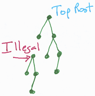
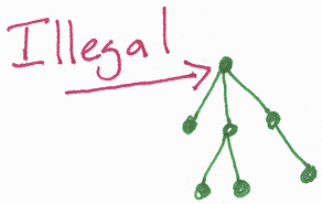
Recall that there are only two real rules in building this tree. One that no root may have more than two children, and two that every root except for the top one must have one and only one parent. For this reason the following trees are illegal.

This tree has a node which has more than one parent.

Illegal binary tree

This tree has a node other than the top one which has no parent.

Illegal binary tree

This tree has a node with three branches.

Illegal binary tree

Note: The last three trees are illegal. They are not real binary trees because they violate one of the rules defining binary trees. Binary trees are a type of graph. All of those illegal binary trees are in fact legal graphs, but are not binary trees.

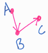
An important concept in graph theory and one that comes into play with trees is that of direction. There are two types of graphs in relation to direction directed graphs and non-directed graphs. If a graph has direction then that is to say that an edge may only be traversed in one direction. An edge which has a direction is usually denoted by an arrow in the direction that the edge may be traversed. For example in this directed graph there is an edge from A to B but there is not an edge from B to A.

Simple directed graph

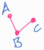
That is as opposed to this non-directed graph which is the same except that the edge which connects A to B also connects B to A.

Simple non-directed graph

Binary trees may be considered directed or they may not. It really depends on the information being modeled. Direction is not an integral part of a tree.
Friday, May 28, 1999 8:33 AM

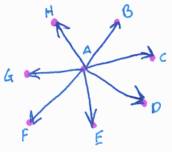
If you have direction though it allows you to introduce the concept of a graph being cyclic or not. If a graph is cyclic than it contains cycles which are routes which allow you to leave one node and return to that same node. The following graph is non-cyclic because obviously once you leave A you cannot get back because there are no paths leading into A. The same holds true for all the other nodes as well.

Simple non-cyclic graph

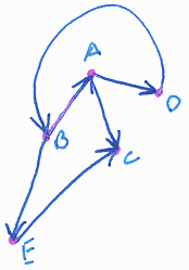
If there is one node in the graph that can be returned to once it has been left (one cycle) then the graph is cyclic. It need not be true that you can get back to all the nodes once you have left them, just one. In the following graph you can go from B to A to D and then back to B again, so B, A and D are on a cycle making the graph cyclic. If you go to C however there are no edges leading out so it cannot be on a cycle. Even though all of the nodes are not in a cycle, the fact that some are makes the graph cyclic.

Simple cyclic graph

Non-directed graphs are by their nature cyclic since every edge goes both ways thereby making it possible to get from A to A if you can get from A to B because you can go from A to B back to A. In fact any non-directed graph can be drawn as a directed graph. Each edge is just doubled and for each non-directed edge A-B there are two new directed edges A-B and B-A.

Equal graphs

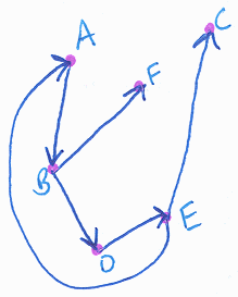
I mentioned that a java scene graph is a directed-acyclic graph; that is to say that is is a directed non-cyclic graph. One final aspect of graphs that you need to be able to understand scene graphs is the idea of a path through a graph. A path is simply a set of edges that you traverse according to the connectivity of the graph. In the following graph for example a simple path is A to B to D to E, this is allowed because each transition is along an edge in the graph. A to B to C would not be allowed because there is no edge B-C.

Graph

For non-cyclic graphs there are a finite number of paths. This makes sense since in a non-cyclic graph once you leave a node you cannot return so eventually you are going to run out of nodes. In cyclic graphs you can have an infinite number of paths since if the graph has a cycle A to B to A then for each path A to B to A to B ... there can be one more path created by adding the next in the series.

The reason that java scene graphs are acyclic trees is that each distinct path through the graph specifies the qualities of exactly one object in the scene. There are are 6 primary types of nodes in a java scene graph and two types of directed edges.

The node types are: (along with the symbol used by the java people to represent them in a scene graph)

Virtual universe
This is the top root node in a java 3d scene graph. It represents an entire plane of virtual existence. An entire scene graph is centered from this node. According to the API it is possible to have a java 3d program with more than one virtual universe but there is no established way to switch between them (kinda like here.) So in general a java 3d program will have one scene graph with one of these at the top.

Locale
The API tutorial says, "A locale object provides a reference point in the virtual universe. Think of a Locale object as being a landmark used to determine the location of visual objects in the virtual universe." Ok, that works for me. As best I can tell locales are located directly underneath the root virtual universe node and act as basepoints from which a person views a scene. All of the java 3d programs that I have seen so far have had a static viewer position and then objects which moved in relation to that.

Group
A group, like its name suggests, allows for the grouping of several nodes. There are two main types of groups as far as I can tell, branch groups and transform groups. A branch group serves as the root for a subgraph, or branch graph as the resulting graph is called. Apparently branch groups serve no real purpose and according to
another tutorial they may be removed once the scene is compiled. It is important to note though that there are two general types of branch graphs, content branch graphs which specify the contents of a scene and view branch graphs which specify aspects of the viewpoint. The other type of grouping object is a transform group which contains information about a shift in the location of an object.

Leaf
All branches of a java 3d scene graph must end in a leaf node. Also the only place that a leaf node may appear is at the end of a branch. There are a variety of things that may be leaf nodes. As I learn more about them I will talk about them. The aspects that the API tutorial lists are the "shape, sound and behavior of visual objects in the virtual universe." Even though a Leaf may have no children it is allowed to reference other objects. The concept of a reference link is described shortly.

Node component
Node components specify aspects of a node. In the API the list of subclasses of NodeComponent is "Appearance, AuralAttributes, ColoringAttributes, DepthComponent, Geometry, ImageComponent, LineAttributes, Material, MediaContainer, PointAttributes, PolygonAttributes, RenderingAttributes, TexCoordGeneration, Texture, TextureAttributes, TransparencyAttributes." As to what this means exactly at the moment, you've got me. I know that a node component can specify the color of an object, and apparently some other stuff as well.

Other objects
You got me, most of these things have no explanation anywhere. I reckon this is everything else. What exactly that might be, I dunno.

In addition to the 6 types of nodes there are two types of edges (kinda.)

Parent/child link
This is an edge in the scene graph. I think the explanation of what an edge is to this point covers what this is and what it specifies. Recall that each node in a java 3d scene graph may have only one parent but may have any number of children (except for leaves which may have no children.)

Reference link
A reference is like a link but not really. The usual rules do not apply. Node components are connected to leaves (which are not allowed to have any children) by references. Also a node component (which as best I can tell is the thing most often referenced) may be referenced by more than one object violating the usual single parent rule. References will be another aspect that will be explored further as more is learned.

To show you what a simple scene graph looks like, courtesy of the API tutorial: There are two main parts branching off of the locale (which is right under the virtual universe at the top) the left branch is a content branch graph (specifying the content of the scene) and the right is a view branch graph (specifying the viewers perspective.) The part that is blue represents what is contained within the class SimpleUniverse which I will talk about later. For now just ignore the dashed line and the color difference.

Simple scene graph

Friday, May 28, 1999 5:06 PM

Another aspect of this project is the viewing of the applet. It is possible to do this using the Java development kit
(JDK), available from sun's site, with the java 3d extension installed. The programs could then be run by loading the java virtual machine. An alternative is the install the Java run-time environment (JRE) which includes the java plug-in which can then be accessesed through a browser and you can run java 3d programs like a normal applet. You will still have to install the 3d extension.

This is important to me because if I want you to be able to see my work via the web I have to put in special tags to call the plug-in to run the applet rather than having the browser do it itself. Surprise, surprise, these tags are complicated (as it seems everything is.) So, I have been reading a specification on how to write tags that are viewable by the java plug-in. Apparently this is handled differently by both IE and netscape and for the moment I am going to worry about the netscape version. If it is not too much trouble though I will do the IE as well. I assume that won't cause too many problems.

I hope soon to move out of the scene graph stuff and into the actual creation of a scene.
Saturday, May 29, 1999 1:26 PM

Let me try this plug-in thing. This ought to be one of the demo applets that I did a quick hack of.

No JDK 1.2 support for APPLET!! No JDK 1.2 support for APPLET!!
Well, it does not seem to work right. Ah well. The netscape version brings up a box and says "Loading java applet..." but it dies around in there. The IE version complains that it doesn't have the plug-in. The program will run as an applet through the appletviewer and as a program through the virtual machine. I don't get it. I don't know enough about how it works yet to really do much debugging. I'll fool around with it more once I've made a simple java 3d program.

I would like to know though why the align="center" parameter doesn't work here or with images. I tried switching it over to align="middle" and it still didn't work. I keep having to use <center> tags.
Saturday, May 29, 1999 2:25 PM

Speaking of the creation of content I am starting to get more into that in the different things that I am working through. The tutorial and the API spec approach it in very different ways. The spec is very thorough and is covering many different aspects of java 3d programming. The tutorial is understandable limiting its scope and only covering certain aspects. The only issue that I have with the tutorial is that they make no reference to the fact that there are other ways to program java 3d. They do disclaim however that the tutorial is intended as a supplement to the spec so if you take that seriously (even though the writing style does not support that assertion) then everything is Ok.

What I will be working on to begin with is compiled-retained mode as opposed to retained mode or immediate mode. I agree with the tutorial though in that talking about more than just compiled retained mode would probably serve little other than to confuse.

What I will be doing is specifying a simple scene graph and the compiler takes care of everything else. Actually what I will be doing is less than that. In a complete minimal java 3d program there is a view graph and if there is anything in the scene a content graph is needed to represent it.

Because much of the work done to create is oft times the same every time java created a class called SimpleUniverse which creates a VirtualUniverse with a simple view branch already created. I included an illustration earlier which has a large section surrounded by a dashed line and blued out. The blue area is what is included in the SimpleUniverse class. All that is left then is for the programmer to create something to go in the scene and attach an appropriate branch group to the existing tree. Even the creation of geometry is taken care of as well. Java includes a test object which is a little cube to stick in the scene.

Keep your fingers crossed. =) I would except that it slows down my tying terribly. This is what I think a simple java 3d program ought to look like:

/**
 * Java 3d programs are an extension of applet most always it seems.
 * I have not heard mention of this being requisite, but for the time
 * being I will respect the trend that I have noticed and when I get
 * a bit more fluent I will deviate.
 * <br><br>
 * For this reason though the AWT toolkit is included since it is one
 * easy way to lay out applets that I am familiar with.
 */
import java.awt.*;

/**
 * The mainframe class is a very handy extension included in the java
 * 3d utilities which allows any applet to run as a standalone
 * application. You will see its usage later.
 */
import com.sun.j3d.utils.applet.MainFrame;

/**
 * The SimpleUniverse I have already explained. It includes a basic
 * scene graph which includes a VirtualUniverse, a Location and a view
 * branch graph.
 */
import com.sun.j3d.utils.universe.SimpleUniverse;

/**
 * ColorCube is a simple cube, 2 meters on a side, with sides:
 * <ul>
 *  <li>front  - red</li>
 *  <li>back   - green</li>
 *  <li>right  - blue</li>
 *  <li>left   - yellow</li>
 *  <li>top    - magenta</li>
 *  <li>bottom - cyan</li>
 * </ul>
 * It is centered around whatever its initial point is.
 */
import com.sun.j3d.utils.geometry.ColorCube;

/**
 * This is most of the java 3d classes; specifically Canvas3D, BranchGroup.
 */
import javax.media.j3d.*;

/**
 * This is about the simplest java 3d program there can be. I included the
 * date as part of the name because I plan to make several simple little
 * applets and the naming will probably get messy.
 *
 * @author Will Holcomb
 */
public class SimplestJava3DApplet_05_29_99 extends java.applet.Applet
{
    /**
     * First include a public constructor which sets up the applet
     */
    public SimplestJava3DApplet_05_29_99()
    {
        /**
	 * Canvas3D is an extension of Canvas created especially to draw
	 * java 3d pictures on. One is needed for any program.
	 * <br><br>
	 * Canvas3D expects a java.awt.GraphicsConfiguration in its
	 * constructor. Why I have to specify null and they couldn't just
	 * default it out I expect is just messiness.
	 */
	Canvas3D drawingCanvas = new Canvas3D(null);

        /**
	 * I have it on the report of Andy that unless the layout used
	 * to hold the java 3d canvas is a BorderLayout then it will not
	 * respond to events at all. This is at the very least a pain
	 * seeing as my personal favorite is the flexibility of the
	 * GridBagLayout. That is another unexplored aspect of the API
	 * that I will worry about later.
	 */
        setLayout(new BorderLayout());

	add("Center", drawingCanvas);

	/**
	 * This creates the scene graph with the ColorCube in it. Though
	 * it is not required that a function createSceneGraph exist the
	 * nomenclature is what is most commonly used. For more on this
	 * function look at its code.
	 * <br><br>
	 * Recall here that all subgraphs (view or content) are rooted in
	 * in a BranchGroup. According to the API specification the only
	 * children of a VirtualUniverse are Locations and the only
	 * children of Locations are BranchGroups.
	 */
	BranchGroup cubeScene = createSceneGraph();

	/**
	 * I mentioned earlier that I was going to be working in Compiled-
	 * Retained Mode. The Retained aspect of the mode is that I am
	 * creating a scene graph and allowing the java 3d engine to take
	 * care of drawing them. What I am doing now is the compiled
	 * aspect.
	 * <br><br>
	 * When a scene graph is compiled its structure is changed into one
	 * that is equivalent but which the compiler can deal with more
	 * efficiently. Compiling does change the structure of the branch
	 * though and makes changing it more difficult if not impossible.
	 * <br><br>
	 * The tutorial recommends only compiling branch groups which are
	 * going to be inserted into Locales and then only compiling them
	 * just before insertion.
	 */
	cubeScene.compile();

	/**
	 * This is the SimpleUniverse which contains the elements discussed
	 * before. It is passed the canvas which is to be drawn on. This is
	 * used in the initialization of the View.
	 */
	SimpleUniverse simpleUniverse = new SimpleUniverse(drawingCanvas);

	/**
	 * Since I am not including any Transform Groups in my scene graph
	 * the ColorCube will start out centered at (0, 0, 0). Likewise my
	 * since my view is not changed I will start out viewing at (0, 0, 0)
	 * which means essentially that I will be inside of the ColorCube,
	 * making it difficult to see much of anything.
	 * <br><br>
	 * For this reason I will back the viewpoint up a bit so that we
	 * can actually see something. The setNominalViewingTransform()
	 * function is one included in the ViewingPlatform class and it sets
	 * the viewpoint back about 2.41 meters along the z axis (straight
	 * back.)
	 */
	simpleUniverse.getViewingPlatform().setNominalViewingTransform();

	/**
	 * Having created a scene and set the view all that is left now is
	 * to graft the content branch group onto the existing tree created
	 * by SimpleUniverse.
	 */
	simpleUniverse.addBranchGraph(cubeScene);
   }

   /**
    * This function specifies the creation of a branch group which contains a
    * ColorCube.
    */
   private BranchGroup createSceneGraph()
   {
       /**
        * All subgraphs must be rooted in a BranchGroup.
	*/
       BranchGroup root = new BranchGroup();

       /**
        * Color cube is descended from javax.media.j3d.Shape3D which is in
	* turn descended from javax.media.j3d.Leaf so what is essentially
	* taking place in this step is that a branch is being created which
	* consists of a single Leaf.
	* <br><br>
	* The .4 that the cube is constructed with specifies the scale of
	* the cube. The default is 1 and the cube has corners at (1, 1, 1)
	* and (-1, -1, -1). This cube will be .8 meters on each side and
	* will have corners at (.4, .4, .4) and (-.4, -.4, -.4).
	*/
       root.addChild(new ColorCube(0.4));

       /**
        * The simple scene is now complete. The root of the graph is
	* returned to the calling function.
	*/
       return root;
   }

   /**
    * When a program is run on the java virtual machine (as opposed to within
    * a web browser or through the appletviewer) the static method main is
    * called.
    */
   public static void main(String[] args)
   {
       /**
        * MainFrame is a class with takes as its initialization list an applet
	* to be displayed and the dimensions to display it as and it simulates
	* the behavior of a browser and allows the applet to be run as a
	* standalone program; very handy.
	*/
       new MainFrame(new SimplestJava3DApplet_05_29_99(), 256, 256);
   }
}
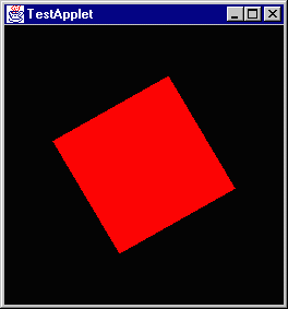
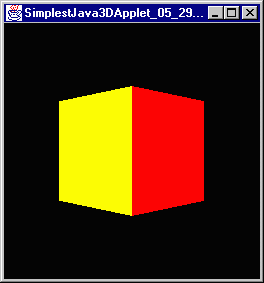
Yippie, it works. =) It is certainly unimpressive, but it works.

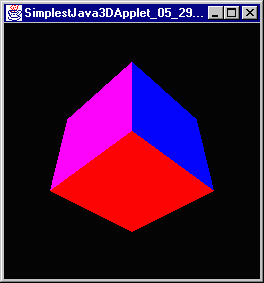
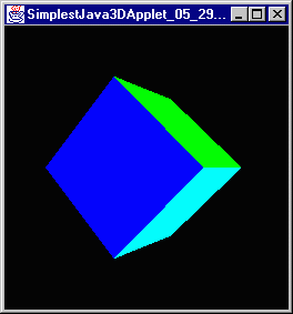
Here's what is looks like:

Applet number one

The whole cube is there, just the way I am looking at it all I can see is one side. I'll try shrinking it down and see if I can get a look at the top. I'm now sure if that's possible since I am looking absolutely straight on. If I were to be able to see the top then likewise I would be able to see the bottom since the viewing angle is the same and it is impossible to see both the top and the bottom at the same time I think.

You may have wondered why I kept sticking html in my comment as I was writing. I have been using the javadoc program in the past alot and it is a very handy utility which is extremely useful. It uses html formatting to produce documentation. For the time being I am going to stop using the html because it makes a mess when the program is being displayed in a browser.

Well, that was my first java 3d program. It wasn't bad at all really. Hopefully I can keep that attitude. I went today and printed another 250 pages of API specification so there's still a long way to go.
Wednesday, June 2, 1999 8:20 AM

I took yesterday off to work on the computer chapter for the Honors Handbook. Today I am going to start moving into learning how to move created objects abound. This is done by inserting a Transform Group into the scene graph. Transform groups control both rotation and translation (movement in space.) They are intialized with a Transform3D object which specifies as transformation matrix.

The Transform3D object is pretty complicated and it includes alot of stuff, but all that I am going to make my business at this point is the three methods rotX(double), rotY(double) and rotZ(double). All angles in java 3d are in radians. These are (as you might guess) the methods for making the matrix represent a rotation about an axis. I'm gonna give them a shot. The only thing that I ought to have to change is my createSceneGraph() function.; just add a TransformGroup at the top. Here is my guess as to what the code ought to look like:

private BranchGroup createSceneGraph()
{
  BranchGroup root = new BranchGroup();
  Transform3D rotate = new Transform3D();
  rotate.rotX(Math.toRadians(45));
  TransformGroup rotationTransform = new TransformGroup(rotate);
  rotationTransform.addChild(new ColorCube(0.4));
  root.addChild(rotationTransform);
  return root;
}
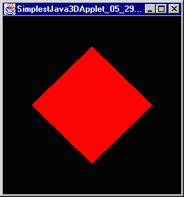
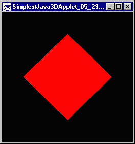
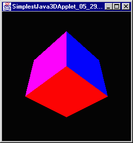
Let's see how that turns out:


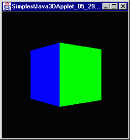
Not shabby at all. About like I expected it to. How's about I rotate it along Y and Z?


Well that works like I thought it would. I wonder if I can specify multiple transforms in one object. In the tutorial they create an object that rotates 45° on the X and then one to rotate 45° on the Z and multiply them together. I wonder if you can do both in once. Here is the code that I am thinking about:
private BranchGroup createSceneGraph()
{
  BranchGroup root = new BranchGroup();
  Transform3D rotate = new Transform3D();
  rotate.rotX(Math.toRadians(45));
  rotate.rotZ(Math.toRadians(45));
  TransformGroup rotationTransform = new TransformGroup(rotate);
  rotationTransform.addChild(new ColorCube(0.4));
  root.addChild(rotationTransform);
  return root;
}
That is as opposed to:
private BranchGroup createSceneGraph()
{
  BranchGroup root = new BranchGroup();
  Transform3D rotateX = new Transform3D();
  rotateX.rotX(Math.toRadians(45));
  Transform3D rotateZ = new Transform3D();
  rotateZ.rotZ(Math.toRadians(45));
  rotateX.mul(rotateZ);
  TransformGroup rotationTransform = new TransformGroup(rotateX);
  rotationTransform.addChild(new ColorCube(0.4));
  root.addChild(rotationTransform);
  return root;
}
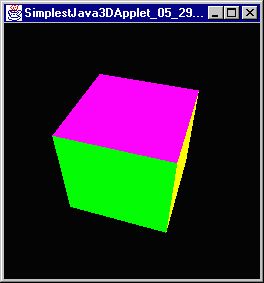
The two programs look like this:


So apparently doing Transform3D.rotZ() overrides the previous Transform3D.rotX(). I don't understand why that would happen and it seems silly to me that it does but I have trouble making serious accusations since I know so little about transformation matrices. I am going to hedge a bet though on what I know of java 3d and say that putting both of those transform groups in the scene graph and not multiplying them together will produce the same picture. Lets give it a run shall we? Here is the code:
private BranchGroup createSceneGraph()
{
  BranchGroup root = new BranchGroup();
  Transform3D rotateX = new Transform3D();
  rotateX.rotX(Math.toRadians(45));
  TransformGroup xRotation = new TransformGroup(rotateX);
  root.addChild(xRotation);
  Transform3D rotateZ = new Transform3D();
  rotateZ.rotZ(Math.toRadians(45));
  TransformGroup zRotation = new TransformGroup(rotateZ);
  xRotation.addChild(zRotation);
  zRotation.addChild(new ColorCube(0.4));
  return root;
}
And I am thinking that ought to look the same as when I multiplied the two transforms together. Let's see:


Yep, I was right. To follow the tutorial lets move on now to animations and behaviors. This requires a brief look at the idea of compiling a scene graph which I mentioned earlier. What compiling does is take a branch and order its nodes into a different structure so that it will compile faster. For example, I just got through producing the same results two different ways. In one I created two transformation matrices and multiplied them together to make one which had the overall affect of them both. In the second I created two transformation matrices and but them both in the scene graph in different transform groups. When the compiler if running the first program it must only do one transformation (the product of the two transformations,) when the compiler is running the second it must do two transformations (one for each transform group.) In order to same on time what the java 3d engine does when a scene graph is compiled is it will do things like take multiple transform groups that are in a row and it will combine them into one so as to reduce the number of transformations that it does.

The reason that this matters now is that because the compiling process changes the structure of the scene graph it is no longer possible for the programmer to work with its contents. Animation behaviors though require that a specific transform in the scene graph be altered. How can this be done? Well, the programmer has to tell the compiler specifically not to fiddle with the groups that she wishes to have access to once the scene is compiled. This is done by setting capability bits for the group node. For this next one we are going to be interested in the ALLOW_TRANSFORM_WRITE bit of Transform group (which is set with the setCapability() method,) which specifies that the data in the transform group may be changed.

An animation is simply changing the transformation by small increments over a period of time. These changes are going to be done by a RotationInterpolator. Interpolators are a set of classes the control most (if not all, I don't know for sure) of the defined behaviors in java 3d. They change things like the position and the orientation and even the appearance of scene objects.

A rotation interpolator uses a special class called an Alpha. Alpha are supposedly complicated little suckers that can do a whole lot of stuff. There is a whole chapter on the in the API spec and it has lots of graphs and stuff in it. I will worry about them more later when I need to.

One final thing to talk about is a BoundingSphere. It java 3d you can create huge worlds with tons of stuff in them. Also you can have bunches and bunches of behaviors. What the java people wanted to avoid was that you would create a world and it would run terribly slow because there were lots of little behaviors all over the place and the sum total of them was lagging the processor. What they did to alleviate this problem is create the idea of a scheduling region. In this case our scheduling region is going to be a sphere though it can be other things as well. Think of the scheduling region as an invisible sphere. If you can see the area where any part of this invisible sphere is then the region is active and whatever the behavior is will be active. If it is not then the behavior is turned off. As the java 3d tutorial say this creates a scenario in which if there is no one in the forest then the tree will not fall.

Yet again the only code that actually needs to be changed is the createSceneGraph() method. Here is my guess as to what the code ought to be:
private BranchGroup createSceneGraph()
{
  BranchGroup root = new BranchGroup();

  TransformGroup rotateGroup = new TransformGroup();

  /**
   * Setting the ALLOW_TRANSFORM_WRITE bit allows the RotationInterpolator
   * to change the extent of the transformation.
   */
  rotateGroup.setCapability(TransformGroup.ALLOW_TRANSFORM_WRITE);

  /**
   * This Alpha object is being intialized with two parameters:
   * The -1 tells it to loop forever.
   * The 4000 tells it to take 4000 milliseconds (4 seconds) to get from
   *  zero to one.
   */
  Alpha fourSecondAlpha = new Alpha(-1, 4000);

  /**
   * This RotationInterpolator is intialized with two values:
   * The first is the Alpha that will be sending its timing signals
   * The second is the TransformGroup that it is going to be altering
   *
   * According to the API this also has the default values of rotating
   * 2 * PI radians (a full circle) and rotation about the axis of
   * identity (whatever that means.)
   */
  RotationInterpolator rotatorBehavior =
     new RotationInterpolator(fourSecondAlpha, rotateGroup);

  /**
   * This BoundingSphere is created with the default values of:
   * centered at (0, 0, 0)
   * radius 1
   */
  BoundingSphere bounds = new BoundingSphere();

  /**
   * This sets the scheduling bounds on the rotation behavior to the area of the
   * bounding sphere.
   */
  rotatorBehavior.setSchedulingBounds(bounds);

  /**
   * Now the bits just have to be stuck together. You can see that the rotation
   * behavior is a child of the transform group that it operates on. This is in
   * addition to the fact that the rotation interpolator has a reference to the
   * same transform group.
   */
  root.addChild(rotateGroup);
  rotateGroup.addChild(new ColorCube(0.4));
  rotateGroup.addChild(rotatorBehavior);

  return root;
}
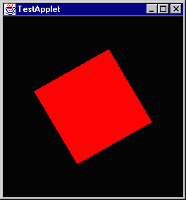
Well, it spins. Apparently the axis of identity is the Y-axis. What that means I know not. If anything I would have guessed it was X, but apparently not. Here's what it looks like:


I wonder if the identity axis changes if you rotate the cube. I'm gonna stick a 45° rotation in before the behavior and see how the thing rotates. Here is my guess at the code:
private BranchGroup createSceneGraph()
{
  BranchGroup root = new BranchGroup();

  Transform3D xRotate = new Transform3D();
  xRotate.rotX(Math.toRadians(45));
  TransformGroup xRotateGroup = new TransformGroup(xRotate);

  TransformGroup rotateGroup = new TransformGroup();
  rotateGroup.setCapability(TransformGroup.ALLOW_TRANSFORM_WRITE);
  Alpha fourSecondAlpha = new Alpha(-1, 4000);
  RotationInterpolator rotatorBehavior =
     new RotationInterpolator(fourSecondAlpha, rotateGroup);
  BoundingSphere bounds = new BoundingSphere();
  rotatorBehavior.setSchedulingBounds(bounds);

  root.addChild(xRotateGroup);
  xRotateGroup.addChild(rotateGroup);
  rotateGroup.addChild(new ColorCube(0.4));
  rotateGroup.addChild(rotatorBehavior);

  return root;
}
It takes for bloody ever for anything to compile here. I am mapping a networked drive on a NT box in the CSc system from the main campus network and it literally takes 3 minutes for something to compile and then 4 or so for it to load and run. This is a pain. It does give me thinking time though and I was wondering what if I changed the nature of the transform group the the rotation behavior is attached to? What would it do then. Lets find out shall we?

First though the results of that last test:


It is a bit hard to tell from the picture but the rotation appears to be independent of the transformation. The cube is not rotation along an axis that would be coming out of the screen at 45°. Another quick question that I have if what it would look like if I moved the transform group to after the rotation. Let me do that real quick:
private BranchGroup createSceneGraph()
{
  BranchGroup root = new BranchGroup();

  Transform3D xRotate = new Transform3D();
  xRotate.rotX(Math.toRadians(45));
  TransformGroup xRotateGroup = new TransformGroup(xRotate);

  TransformGroup rotateGroup = new TransformGroup();
  rotateGroup.setCapability(TransformGroup.ALLOW_TRANSFORM_WRITE);
  Alpha fourSecondAlpha = new Alpha(-1, 4000);
  RotationInterpolator rotatorBehavior =
     new RotationInterpolator(fourSecondAlpha, rotateGroup);
  BoundingSphere bounds = new BoundingSphere();
  rotatorBehavior.setSchedulingBounds(bounds);

  root.addChild(rotateGroup);
  rotateGroup.addChild(xRotateGroup);
  rotateGroup.addChild(rotatorBehavior);
  xRotateGroup.addChild(new ColorCube(0.4));

  return root;
}
Which comes out spinning in the same way as the first one (not the one right before this) but it is turned on its corner. It looks like this:


There's some data to be processed there. I think I get how this is working. I want to see though what happens when I screw with the transform group that has the behavior on it. To this point it have only been a default which doesn't actually do any transforming. All the transforming has been by the rotator behavior. SO I will make the transform group that the behavior is operating on a 45° rotate along X. Here is the code:
private BranchGroup createSceneGraph()
{
  BranchGroup root = new BranchGroup();

  Transform3D xRotate = new Transform3D();
  xRotate.rotX(Math.toRadians(45));
  TransformGroup rotateGroup = new TransformGroup(xRotate);
  rotateGroup.setCapability(TransformGroup.ALLOW_TRANSFORM_WRITE);
  Alpha fourSecondAlpha = new Alpha(-1, 4000);
  RotationInterpolator rotatorBehavior =
     new RotationInterpolator(fourSecondAlpha, rotateGroup);
  BoundingSphere bounds = new BoundingSphere();
  rotatorBehavior.setSchedulingBounds(bounds);

  root.addChild(rotateGroup);
  rotateGroup.addChild(rotatorBehavior);
  rotateGroup.addChild(new ColorCube(0.4));

  return root;
}
It appears that yet again when things get weird java 3d just ignores it. The cube looks just like the first one which had no transformation at all. Apparently the properties of the transformation matrix are ignored. Again not how I would have done it but I am no expert in matrices or math so maybe it was too complicated.

There is a longer constructor for RotationInterpolator which I think will let me change how the thing rotates (it has too if any changes can be made.) Ok, to change aspects of the rotation you use the extended constructor. It takes five arguments:
  1. The alpha specifying the timing
  2. The TransformGroup being modified
  3. A Transform3D representing the axis of rotation
  4. The minimum angle to be rotated from
  5. The maximum angle to rotate to
If I get this right then this code ought to run the same as the original (and this last one for that matter.)
private BranchGroup createSceneGraph()
{
  BranchGroup root = new BranchGroup();

  Transform3D defaultAxis = new Transform3D();
  TransformGroup rotateGroup = new TransformGroup();
  rotateGroup.setCapability(TransformGroup.ALLOW_TRANSFORM_WRITE);
  Alpha fourSecondAlpha = new Alpha(-1, 4000);
  RotationInterpolator rotatorBehavior =
     new RotationInterpolator(fourSecondAlpha, rotateGroup, defaultAxis,
         (float)0, (float)(Math.PI * 2));
  BoundingSphere bounds = new BoundingSphere();
  rotatorBehavior.setSchedulingBounds(bounds);

  root.addChild(rotateGroup);
  rotateGroup.addChild(rotatorBehavior);
  rotateGroup.addChild(new ColorCube(0.4));

  return root;
}
and it do. If you are wanting to try out any of these and don't want to use the big long commented piece of code that I originally had then here it is commentless. Just plug in the createSceneGraph() function that you want to use.
import java.awt.*;
import com.sun.j3d.utils.applet.MainFrame;
import com.sun.j3d.utils.universe.SimpleUniverse;
import com.sun.j3d.utils.geometry.*;
import javax.media.j3d.*;
import javax.vecmath.*;

public class TestApplet extends java.applet.Applet
{
    public TestApplet()
    {
        Canvas3D drawingCanvas = new Canvas3D(null);
        setLayout(new BorderLayout());
        add("Center", drawingCanvas);
        BranchGroup cubeScene = createSceneGraph();
        cubeScene.compile();
        SimpleUniverse simpleUniverse = new SimpleUniverse(drawingCanvas);
        simpleUniverse.getViewingPlatform().setNominalViewingTransform();
        simpleUniverse.addBranchGraph(cubeScene);
   }

   private BranchGroup createSceneGraph()
   {
   }

   public static void main(String[] args)
   {
       new MainFrame(new TestApplet(), 256, 256);
   }
}
It is significantly shorter without the comments.
Thursday, June 3, 1999 8:50 AM

This brings me to the end of the section on scene graphs and behaviors and stuff. There are a series of questions to answer. I reckon I'll give them a spin.
  1. In the program that multiplies two transforms together what would be the difference if you switched the order of the transforms?

    I don't know really. let me try it and find out. I honestly don't know if matrix multiplication is a commutative property (commutative?, I mean a x b = b x a.) I'll compare these two scene graphs.
    private BranchGroup createSceneGraph()
    {
      BranchGroup root = new BranchGroup();
      Transform3D rotateX = new Transform3D();
      rotateX.rotX(Math.toRadians(30));
      Transform3D rotateZ = new Transform3D();
      rotateZ.rotZ(Math.toRadians(60));
      rotateX.mul(rotateZ);
      TransformGroup rotationTransform = new TransformGroup(rotateX);
      rotationTransform.addChild(new ColorCube(0.4));
      root.addChild(rotationTransform);
      return root;
    }
    
    and
    private BranchGroup createSceneGraph()
    {
      BranchGroup root = new BranchGroup();
      Transform3D rotateX = new Transform3D();
      rotateX.rotX(Math.toRadians(30));
      Transform3D rotateZ = new Transform3D();
      rotateZ.rotZ(Math.toRadians(60));
      rotateZ.mul(rotateX);                               // Note that these two are switched
      TransformGroup rotationTransform = new TransformGroup(rotateZ);  // and this is changed
      rotationTransform.addChild(new ColorCube(0.4));
      root.addChild(rotationTransform);
      return root;
    }
    
    And the server that my compiler is on just went offline for whatever reason so I can't do diddly squat. I reckon I'll write the code to test these questions and then maybe I can get on to check them later.

    Ok, time has passed and it is back now and yes, the order of transformations does matter as these two shots show.
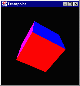
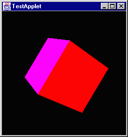
    30x60 60x30
  2. In the program which has a two transform groups, one of which has an animation behavior attached, how does it affect rendering to switch the order of the transform groups?

    I already did this one just for my own affectation. The cube consistently rotated along the same axis relative to its geometry regardless of how it was rotated.

  3. Can you compile the rotation and the spin of the following program into one object?
    private BranchGroup createSceneGraph()
    {
      BranchGroup root = new BranchGroup();
    
      Transform3D xRotate = new Transform3D();
      xRotate.rotX(Math.toRadians(30));
      Transform3D zRotate = new Transform3D();
      zRotate.rotZ(Math.toRadians(60));
      xRotate.mul(zRotate);
      TransformGroup xRotateGroup = new TransformGroup(xRotate);
    
      TransformGroup rotateGroup = new TransformGroup();
      rotateGroup.setCapability(TransformGroup.ALLOW_TRANSFORM_WRITE);
      Alpha fourSecondAlpha = new Alpha(-1, 4000);
      RotationInterpolator rotatorBehavior =
         new RotationInterpolator(fourSecondAlpha, rotateGroup);
      BoundingSphere bounds = new BoundingSphere();
      rotatorBehavior.setSchedulingBounds(bounds);
    
      root.addChild(rotateGroup);
      rotateGroup.addChild(xRotateGroup);
      rotateGroup.addChild(rotatorBehavior);
      xRotateGroup.addChild(new ColorCube(0.4));
    
      return root;
    }
    
    Umm, I certainly don't know how to. When I added rotation behavior to a TransformGroup that had transformation information in it the transformation information was ignored. I wouldn't think that they wouldn't ask the question if it wasn't possible, but I don't know how. I'll send Andy a message and ask him, maybe his knowledge includes how.

    The usage of Transform3D is beginning to confuse me. I tried to change the axis of rotation using the following code and it didn't have any affect.
    private BranchGroup createSceneGraph()
    {
      BranchGroup root = new BranchGroup();
    
      Transform3D defaultAxis = new Transform3D();
      defaultAxis.rotY(Math.toRadians(45));       // This has no apparent affect
      TransformGroup rotateGroup = new TransformGroup();
      rotateGroup.setCapability(TransformGroup.ALLOW_TRANSFORM_WRITE);
      Alpha fourSecondAlpha = new Alpha(-1, 4000);
      RotationInterpolator rotatorBehavior =
         new RotationInterpolator(fourSecondAlpha, rotateGroup, defaultAxis,
             (float)0, (float)(Math.PI * 2));
      BoundingSphere bounds = new BoundingSphere();
      rotatorBehavior.setSchedulingBounds(bounds);
    
      root.addChild(rotateGroup);
      rotateGroup.addChild(rotatorBehavior);
      rotateGroup.addChild(new ColorCube(0.4));
    
      return root;
    }
    
    So I want to write a little driver to find out what the information is inside of the thing by default. Apparently it contains a 3x3 matrix of floats representing something which I have as of yet to figure out. I'm going to print it out and maybe get a clue. Here is that program:
    import javax.media.j3d.*;
    import javax.vecmath.*;
    
    public class MatrixPrint
    {
      public static void main(String [] arguments)
      {
        Matrix3f matrix = new Matrix3f();
        Transform3D defaultTransform = new Transform3D();
    
        defaultTransform.get(matrix);
    
        System.out.println("\t|\t 1\t 2\t 3");
        System.out.println("-----------------------------------");
        System.out.println("1\t|\t" + matrix.m00 + "\t" + matrix.m01 + "\t" + matrix.m02);
        System.out.println("2\t|\t" + matrix.m10 + "\t" + matrix.m11 + "\t" + matrix.m12);
        System.out.println("3\t|\t" + matrix.m20 + "\t" + matrix.m21 + "\t" + matrix.m22);
      }
    }
    
    And the result looks like this:
            |        1       2       3
    -----------------------------------
    1       |       1.0     0.0     0.0
    2       |       0.0     1.0     0.0
    3       |       0.0     0.0     1.0
    
    Now I know that thing is called an identity matrix but as for what that means I know very little. Maybe the web can provide some help.

    Ok, this matrix is the identity matrix and what it is good for (well I don't know that this is useful;) a property of the identity matrix is that any matrix multiplied by this matrix produces the same matrix. A * I = A = I * A. I got this little spiel on matrix multiplication:
        Now I'll see if I can explain matrix multiplication to you.  Let's say we
        have two matrices A and B:
    
            1  2  2        3  4  5  
            4  7  6        5  9  9
            5  6  0        2  7  3
    
               A              B
    
        To multiply them together, we take a row from A and a column from B and
        multiply each entry in the row and the column together, and then add up what
        we get.  The result will be a new 3x3 matrix:
    
           1*3 + 2*5 + 2*2   1*4 + 2*9 + 2*7   1*5 + 2*9 + 2*3      17  36  29
           4*3 + 7*5 + 6*2   4*4 + 7*9 + 6*7   4*5 + 7*9 + 6*3  =   59 121 101
           5*3 + 6*5 + 0*2   5*4 + 6*9 + 0*7   5*5 + 6*9 + 0*3      45  74  79
    
                          A*B                                         A*B
    
        Notice that multiplication of matrices isn't commutative: if you multiply
        B*A you'll get something completely different, so A*B doesn't equal B*A.
        Also notice that you can't multiply a 3x4 matrix by a 5x2 matrix.  If you
        have a something-by-n matrix, you can only multiply it on the right by an
        n-by-something-else matrix.  By the way, I think multiplication of matrices
        is something you'd understand a lot better if you got someone to actually
        show it to you, instead of trying to just tell you like I did.
    
    Makes sense to me. I don't have a clue what it would be useful for, but it makes sense.

  4. Use this code to perform a translation:
    Transform3D translate = new Transform3D();
    Vector3f translationVector = new Vector3f((float)0, (float)1, (float)0);
    translate.setTransform(translationVector);
    
    If you change the position of the translation in the scene graph do you expect to see a change? Absolutely; it is the same as asking if turn 45°, walk 2 meters, turn 90°, walk 1 meter is the same as turn 135°, walk 3 meters or walk 3 meters, turn 135°. Each one will put you at a different point as should positioning the transformation differently. I will use the two following test scene graphs:


Friday, June 4, 1999 8:39 AM

I am going to take a brief sabbatical from the tutorial and move off for a bit into the actual work that Andy did this last semester. I am not to a point yet where I am going to understand all that he did but I am going to see if I can get a rough grasp. Honestly I am getting bogged down in these transformation matrices and I don't know what they mean and I want out from under it for a bit.

As I understand it at this point Andy's class structure lines up like this: The first thing that I am going to do is run through robot.java line by line and see if I can construct a logical picture of what it is doing.

He starts out including the usual files.
import javax.media.j3d.*;
import javax.vecmath.*;
import java.lang.*;
import Joint;
import Axis;
import Block;
import com.sun.j3d.utils.geometry.Cylinder;
import com.sun.j3d.utils.geometry.Sphere;
import java.awt.event.*;
Then he creates a default constructor:
public class Robot implements MovementRequestListener {
And he creates the geometry that he will need to build the scene graph:
private BranchGroup RobotBase = new BranchGroup();//the root of the scenegraph
private TransformGroup RobotBaseTG = new TransformGroup();//Transform from root to first node
private Appearance ltBlue = new Appearance();//a light blue appearance
private Appearance dkBlue = new Appearance();//a darker blue appearance
private Joint Joint0;//Joint object representing the 0th joint
private Joint Joint1;//Joint object representing the 1st joint
private Joint Joint2;//Joint object representing the 2nd joint
private Joint Joint3;//Joint object representing the 3rd joint
private Joint Joint4;//Joint object representing the 4th joint
private Joint Joint5;//Joint object representing the 5th joint
private Joint Joint6;//Joing object representing the 6th joint
Claw claw;//a Claw object that is the end effector for this robot
Now he declares a function within the class which sets the ALLOW_CHILDREN_WRITE capability on a specified group.
final private void addWriteCap(Group temp) {
temp.setCapability(Group.ALLOW_CHILDREN_WRITE);
}
This function is equivalent to Math.toRadians(int degrees). I reckon he didn't know about that.
final private float degToRad(float deg)  {
return (float)(deg * 2 * Math.PI / 360);
}
This class that sets up his scene graph I think. He identifies the variable as such:
private void buildRobot() {
RobotBase.setCapability(BranchGroup.ALLOW_CHILDREN_WRITE);
RobotBaseTG.setCapability(TransformGroup.ALLOW_TRANSFORM_WRITE
                        | TransformGroup.ALLOW_PICK 
			| TransformGroup.ALLOW_PICKABLE_WRITE
			| TransformGroup.ALLOW_PICKABLE_READ
		      );
addWriteCap(RobotBaseTG);

Matrix3f tempM = new Matrix3f(0f, 1f, 0f,
                              0f, 0f, 1f,
			      1f, 0f, 0f);

Joint0 = new Joint(tempM, new Vector3f(0f, .6604f, 0f));
Joint1 = new Joint(((float)(Math.PI / 2)), (-(float)(Math.PI / 2)), 0,     0,      -160, 160);
Joint2 = new Joint(0f,                     0f,                      .432f, .1495f, -225, 45);
Joint3 = new Joint(((float)(Math.PI / 2)), ((float)(Math.PI / 2)),  0f,    0f,     -45,  225);
Joint4 = new Joint(0f,                     (-(float)(Math.PI / 2)), 0f,    .432f,  -110, 170);
Joint5 = new Joint(0f,			   ((float)(Math.PI / 2)),  0f,	   0f,     -100, 100);
Joint6 = new Joint(0f,			   0f,                      0f,    .0565f, -266, 266);

//build the links...
//starting with the base
Transform3D Link0T = new Transform3D();
Link0T.rotX((float)(Math.PI * .5));
Link0T.setTranslation(new Vector3f(0f, 0f, -.3302f));
TransformGroup Link0TG = new TransformGroup(Link0T);
addWriteCap(Link0TG);
Cylinder Link0 = new Cylinder(.07f, .6604f, ltBlue);
Link0TG.addChild(Link0);

//then the short cylinder around the bottom of the base
Cylinder Link0a = new Cylinder(.3f, .1f, dkBlue);
Transform3D Link0aT = new Transform3D();
Link0aT.rotX((float)(Math.PI * .5));
Link0aT.setTranslation(new Vector3f(0f, 0f, -.6104f));
TransformGroup Link0aTG = new TransformGroup(Link0aT);
addWriteCap(Link0aTG);
Link0aTG.addChild(Link0a);

//Link1, aka Shoulder
Transform3D Link1T = new Transform3D();
Link1T.rotX(-(float)(Math.PI * .5));
Link1T.setTranslation(new Vector3f(0f, 0f, ((float)(.1495 * .5))));
TransformGroup Link1TG = new TransformGroup(Link1T);
addWriteCap(Link1TG);
Cylinder Link1 = new Cylinder(.07f, (float)(2*.1495), dkBlue);
Link1TG.addChild(Link1);

//now for the second link -- upper arm...
Transform3D Link2T = new Transform3D();
Link2T.setTranslation(new Vector3f((-(float)(.4325 * .5)), 0f, 0f));
TransformGroup Link2TG = new TransformGroup(Link2T);
addWriteCap(Link2TG);
Block Link2 = new Block((float)(.4325 * .5), .09f, .07f, ltBlue);
Link2TG.addChild(Link2);

//add link3A....a thingy to cover up the weird joint....
Transform3D Link3aT = new Transform3D();
Link3aT.rotX((float)(Math.PI * .5));
Cylinder Link3a = new Cylinder(.07f, .15f, dkBlue);
TransformGroup Link3aTG = new TransformGroup(Link3aT);
addWriteCap(Link3aTG);
Link3aTG.addChild(Link3a);

//and Link3...
Transform3D Link3T = new Transform3D();
Link3T.setTranslation(new Vector3f(0f, (float)(.4325 * .5), 0f));
TransformGroup Link3TG = new TransformGroup(Link3T);
addWriteCap(Link3TG);
Block Link3 = new Block(.07f, (float)(.4325 * .5), .06f, ltBlue);
Link3TG.addChild(Link3);

// add link4...the sphere to which the EE attaches
Transform3D Link4T = new Transform3D();
TransformGroup Link4TG = new TransformGroup(Link4T);
addWriteCap(Link4TG);
Sphere Link4 = new Sphere(((float)(.0565)), dkBlue);
Link4TG.addChild(Link4);

//next, string all the joints together...
RobotBaseTG.addChild(Joint0);
Joint0.getTransformGroup().addChild(Joint1);
Joint1.getTransformGroup().addChild(Joint2);
Joint2.getTransformGroup().addChild(Joint3);
Joint3.getTransformGroup().addChild(Joint4);
Joint4.getTransformGroup().addChild(Joint5);
Joint5.getTransformGroup().addChild(Joint6);

//then add the links to the joints...
Joint0.getTransformGroup().addChild(Link0TG);
Joint0.getTransformGroup().addChild(Link0aTG);
Joint1.getTransformGroup().addChild(Link1TG);
Joint2.getTransformGroup().addChild(Link2TG);
Joint2.getTransformGroup().addChild(Link3aTG);
Joint4.getTransformGroup().addChild(Link3TG);
Joint5.getTransformGroup().addChild(Link4TG);

//then add the claw
claw = new Claw(ltBlue, dkBlue);
Joint6.getTransformGroup().addChild(claw.getClawBG());
//and finally add the whole tree to the root of the robot graph
RobotBase.addChild(RobotBaseTG);
}
It looks really complicated but I think that by and large that is just because of the amount of information. All that he is doing is building a scene graph.

This next function sets the color attributes for his colors.
private void keepUpAppearances() {
ltBlue.setColoringAttributes(new ColoringAttributes(.5f, .6f, .7f, 0));
dkBlue.setColoringAttributes(new ColoringAttributes(0f, 0f, 1.0f, 100));
}
This is just an accessor method for the base of the robot.
public BranchGroup getRobotGraph() {
return RobotBase;
}
This next function I know fairly well because it is the required by my parser. This just allows the robot to handle movement requests.
  
public void movementRequested(MovementRequestEvent e) {
switch(e.getID()) {

case MovementRequestEvent.ROTATE:
  //this one causes the robot to rotate the specified angles and appear at the new position
  Joint1.addTheta(e.arg[0]);
  Joint2.addTheta(e.arg[1]);
  Joint3.addTheta(e.arg[2]);
  Joint4.addTheta(e.arg[3]);
  Joint5.addTheta(e.arg[4]);
  Joint6.addTheta(e.arg[5]);
  break;

/*case MovementRequestEvent.ROTATE:
//this will eventually be an animated version of ROTATE
  Joint0.moveJoint(e.arg[0]);
  Joint1.moveJoint(e.arg[1]);
  Joint2.moveJoint(e.arg[2]);
  Joint3.moveJoint(e.arg[3]);
  Joint4.moveJoint(e.arg[4]);
  Joint5.moveJoint(e.arg[5]);
  break;

case MovementRequestEvent.MOVETO:
//this takes care of moving to a particular point
  processVector(stuff......);
  break;
*/

case MovementRequestEvent.RESET:
//this will return the robot to its original position
  Joint1.reset();
  Joint2.reset();
  Joint3.reset();
  Joint4.reset();
  Joint5.reset();
  Joint6.reset(); 
  break;  

case MovementRequestEvent.TOGGLEAXIS:
//this one toggles a visual representation of the axis for each joint of the robot
  switch(e.arg[0]) {
  case 0:
   Joint0.toggleAxis();
   break;
  case 1:
   Joint1.toggleAxis();
   break;
  case 2:
   Joint2.toggleAxis();
   break;
  case 3:
   Joint3.toggleAxis();
   break;
  case 4:
   Joint4.toggleAxis();
   break;
  case 5:
   Joint5.toggleAxis();
   break;
  case 6:
   Joint6.toggleAxis();
   break;
  }
  break;
}
}

private Transform3D processVector(float x, float y, float z, float aboutX, float aboutY, float aboutZ) {
/*Written by Andy Trent
Input:  x:the new x coordinate for the EE
y:the new y coordinate for the EE
z:the new z coordinate for the EE
aboutX:Any rotation about the X-axis for the new position
aboutY: Any rotation about the Y-axis for the new position
aboutZ: Any rotation about the Z-axis for the new position
Output:  returns a Transform3D that is a transformation to the new coordinate frame of joint6
Variables:Xrot:  Transform3D with the new X rotation matrix
Yrot:  Transform3D with the new Y rotation matrix
Zrot:  Transform3D with the new Z rotation matrix
result: Transform3D built from all the rotations and the translation
This method takes the parameters of the new position for the EE and creates a transformation 
to that point.  This will later be input into the inverse kinematics algorithm to compute the
path.*/

Transform3D Xrot = new Transform3D();
Transform3D Yrot = new Transform3D();
Transform3D Zrot = new Transform3D();
Transform3D result = new Transform3D();
Xrot.rotX(degToRad(aboutX));
Yrot.rotY(degToRad(aboutY));
Zrot.rotZ(degToRad(aboutZ));
result.mul(Xrot);
result.mul(Yrot);
result.mul(Zrot);
result.setTranslation(new Vector3f(x, y, z));
return result;
}

public Robot()  {
/*Written by Andy Trent
Input:  none
Output:  None
This is the constructor for the robot.  It builds the scene-graph and sets up the colors. 
From that point, the robot just sits and waits for events.*/

keepUpAppearances();
buildRobot();
}
}
Umm, nevermind on the starting this now, I'll do a bit more math learning first.

How about this:

To translate a point (x, y, z) by the vector
  x'   1 0 0 tx     x
  y' = 0 1 0 ty  x  y
  z'   0 0 1 tz     z
  w'   0 0 0 1      1
Interesting eh, how about this:

Scaling matrix:
  sx 0  0  0
  0  sy 0  0
  0  0  sz 0
  0  0  0  1
Transformation matrix:
  1     0     0     0
  0   cos T -sin T  0
  0   sin T  cos T  0
  0     0     0     0

Sunday, June 6, 1999 12:40 PM

Ok, I'm getting bit spastic and branching off into too much stuff without sufficient focus to get much accomplished. I am going to talk just about 3D graphics math for a bit. I went into the library yesterday and got the book Fundamentals of Three-dimensional Computer Graphics, written in 1989 by Alan Watt. The book, as I expected begins with an explanation of transformation matrices. I am going to go throught that and summarize.

Transformation matrices are used to deal with a subset of transformations known as linear transformations. The most common linear transformations are translation (changing position,) scaling (changing size,) and rotation (changin orientation.) Java 3d uses what is called a right handed coordinate system. The +X-axis heads off the screen to the right, the +Y-axis goes straight up, and the +Z-axis comes out of the screen at the viewer.

That is the base coordinate system at least. Transformations on the base coordinate system produce not only new points but also a new coordinate system. This is useful for modeling for several reasons. Take this robot project for instance, we have an arm comprised of 6 joints. For simplicity sake lets think of it for a minute as a human are which has three main joints: the shoulder, the elbow and the wrist. Let's say you are dealing with the hand, the hand could be defined in relation to the shoulder, but that isn't necessarily the best way to do it. As I am sitting here typing my arms are moving at my shoulder some, but it is not affecting the position of my hands becasue my elbow and writs are compensating and keeping my hands in the same position. If my hands are defined in relation to my wrist however when I change the position of my wrist I change the position of my hand or at the lest I change the angle. The way that the robot is set up each joint is defined in a coordinate system relative to the joint before it.

I hope that made sense, I'll talk more about it later and try to draw some pictures.

As I said earlier the most common operations in three-dimensional graphics are translation, scaling and rotation. These functions are represneted with the following equations performed on the point V(x, y, z) to get the new transformed point V'(x', y', z'). A new coordinate system was developed so the these three types of transforms could be represented uniformly. Called homogenous coordinates, the point P(x, y, z) is represented as P(X, Y, Z, w) for w not = 0. x = X / w, y = Y / w, z = Z / w. w is called the scaling factor and for computer graphics it is always taken to be 1, so when w = 1 x = X, y = Y, and z = Z.

The idea of a identity matrix comes into play again. Recall that an identity matrix is a (square?) matrix of all 0's except for the top-left to bottom-right diagonal which as all 1's. In matrix multiplication a matrix multiplied by an identity matrix of the appropriate size will produce that matrix again; A * I = A = I * A.

To briefly touch on multiplying matrices since I have never done this before.
Here is a brief tutorial on matrices that a pulled from mathoracle.com. The part on multiplying is this:

Matrix Multiplication: Given a matrix A with dimension mxn and another matrix B with dimension nxr, the product C = A x B of matrices is mxr matrix whose element [element in ith row, jth column] is product of ith row of A and jth column of B.


A homogemnous coordinate V(x, y, z, w) can be represented as a 1x4 matrix:
  [x, y, z, w]
and since in 3d graphics w is always 1 a point in the scene can be represented as:
  [x, y, z, 1]
A transform from point V to V' can be written as V' = V * M where M is the transformation matrix. I mentioned this earier, but the form of transformation matrices is this: The use homogenous coordinates allows all transformations to be of the form V * M = V' where V is the original point, M is the transformation matrix and V' is the new point. As java3d has already suggested transformations may be combined.
 for:
    [x'  y'  z'  w'] = [x  y  z  w] * M1
 and
    [x''  y'' z'' w''] = [x'  y'  z'  w'] * M2
 and
    M3 = M1 * M2
 then
    [x''  y''  z''  w''] = [x  y  z  w] * M3
As I have mentioned before matrix multiplications are not commutative so M1 * M2 != M2 * M1. So paying attention to the order matters.

The general form for a transformation matrix is this:
   A11  A12  A13  0
   A21	A22  A23  0
   A31	A32  A33  0
   Tx   Ty   Tz   1
Where the 3x3 upper left submatrix A specifies the net scaling and rotation and the 1x3 bottom left submatrix T specifies the translation.

Another explanation of the transformation matrix is this: (thank you to Mr. Matt Estes for this)
   Xx  Yx  Zx  0
   Xy  Yy  Zy  0
   Xz  Yz  Zz  0
   Wx  Wy  Wz  1
Where each of the columns X, Y and Z define an axis for a coordinate space and each is assumed to be a normal for that axis so an object drawn in them will have a whatever their length is as 1 unit. The bottom row W then is the origin of this coordinate system relative to the origin. The essence of the two explanations is the same and each will affect an object in the same way.

I am going to do another quick test driver program and theorize what its output ought to be and see if I can guess. I wrote one earlier that got a 3x3 matrix which I assume is the the net scaling and rotation. I am going to get the 4x4 now and check it.
import javax.media.j3d.*;
import javax.vecmath.*;

public class MatrixPrint
{
    public static void main(String [] arguments)
    {
         Matrix4d matrix = new Matrix4d();
         Transform3D transform = new Transform3D();

         transform.get(matrix);

         System.out.println("Initial matrix:");
         printMatrix(matrix);
         System.out.println("");

         transform.rotX(Math.toRadians(90));
         transform.get(matrix);

         System.out.println("Post 90 rotate on X");
         printMatrix(matrix);
         System.out.println("");

         transform.rotY(Math.toRadians(90));
         transform.get(matrix);

         System.out.println("Post 90 rotate on Y");
         printMatrix(matrix);
         System.out.println("");

         transform.rotZ(Math.toRadians(90));
         transform.get(matrix);

         System.out.println("Post 90 rotate on Z");
         printMatrix(matrix);
         System.out.println("");
    }

    public static void printMatrix(Matrix3f matrix)
    {
         System.out.println("\t|\t 1\t 2\t 3");
         System.out.println("-----------------------------------");
         System.out.println("1\t|\t" + matrix.m00 + "\t" + matrix.m01 + "\t" + matrix.m02);
         System.out.println("2\t|\t" + matrix.m10 + "\t" + matrix.m11 + "\t" + matrix.m12);
         System.out.println("3\t|\t" + matrix.m20 + "\t" + matrix.m21 + "\t" + matrix.m22);
    }

    public static void printMatrix(Matrix4d matrix)
    {
         System.out.println("\t|\t 1\t 2\t 3\t 4");
         System.out.println("-----------------------------------------------------");
         System.out.println("1\t|\t" + matrix.m00 + "\t" + matrix.m01
	                      + "\t" + matrix.m02 + "\t" + matrix.m03);
         System.out.println("2\t|\t" + matrix.m10 + "\t" + matrix.m11
	                      + "\t" + matrix.m12 + "\t" + matrix.m13);
         System.out.println("3\t|\t" + matrix.m20 + "\t" + matrix.m21
	                      + "\t" + matrix.m22 + "\t" + matrix.m23);
         System.out.println("4\t|\t" + matrix.m30 + "\t" + matrix.m31
	                      + "\t" + matrix.m32 + "\t" + matrix.m33);
    }
}
My guesstamates are pretty straight forward, all I have to do is remember what sin(90°) and cos(90°) is... I think it's 1 and 0 respectively so they ought to come out like this:
   1  0  0  0       1  0  0  0       0  0 -1  0       0  1  0  0
   0  1  0  0       0  0  1  0       0  1  0  0      -1  0  0  0
   0  0  1  0       0 -1  0  0       1  0  0  0       0  0  1  0
   0  0  0  1       0  0  0  1       0  0  0  1       0  0  0  1
How did they actually come out?
Initial matrix:
        |        1       2       3       4
-----------------------------------------------------
1       |       1.0     0.0     0.0     0.0
2       |       0.0     1.0     0.0     0.0
3       |       0.0     0.0     1.0     0.0
4       |       0.0     0.0     0.0     1.0

Post 90 rotate on X
        |        1       2       3       4
-----------------------------------------------------
1       |       1.0     0.0     0.0     0.0
2       |       0.0     6.123233995736766E-17   -1.0    0.0
3       |       0.0     1.0     6.123233995736766E-17   0.0
4       |       0.0     0.0     0.0     1.0

Post 90 rotate on Y
        |        1       2       3       4
-----------------------------------------------------
1       |       6.123233995736766E-17   0.0     1.0     0.0
2       |       0.0     1.0     0.0     0.0
3       |       -1.0    0.0     6.123233995736766E-17   0.0
4       |       0.0     0.0     0.0     1.0

Post 90 rotate on Z
        |        1       2       3       4
-----------------------------------------------------
1       |       6.123233995736766E-17   -1.0    0.0     0.0
2       |       1.0     6.123233995736766E-17   0.0     0.0
3       |       0.0     0.0     1.0     0.0
4       |       0.0     0.0     0.0     1.0
Let me translate those and round the 6*10^-17 to 0.
Projected:
   1  0  0  0       1  0  0  0       0  0 -1  0       0  1  0  0
   0  1  0  0       0  0  1  0       0  1  0  0      -1  0  0  0
   0  0  1  0       0 -1  0  0       1  0  0  0       0  0  1  0
   0  0  0  1       0  0  0  1       0  0  0  1       0  0  0  1

Actual:
   1  0  0  0       1  0  0  0       0  0  1  0       0 -1  0  0
   0  1  0  0       0  0 -1  0       0  1  0  0       1  0  0  0
   0  0  1  0       0  1  0  0      -1  0  0  0       0  0  1  0
   0  0  0  1       0  0  0  1       0  0  0  1       0  0  0  1
I was right on except that the signs are wrong on all the ones. I wonder why. I think I'll try a rotate on 45° for each axis.

Ok, I tried it for the cases (sinT, cosT) -> 50° (+,+), 170° (+,-), 210° (-,-), and 300° (-,+) and in all cases the sin figure was the negative of what it was supposed to be. I updated the driver program a bit to speed testing up; I made it so the angle to rotate by could be put on the command line and I fixed it so the numbers were truncated at two decimal places so they fit in columns right. Here is that code:
import javax.media.j3d.*;
import javax.vecmath.*;
import java.text.*;

public class MatrixPrint
{
    protected static DecimalFormat twoDigitFormat = new DecimalFormat();

    public static void main(String [] arguments)
    {
         Matrix4d matrix = new Matrix4d();
         Transform3D transform = new Transform3D();
         int angle = 0;

         twoDigitFormat.setMaximumFractionDigits(2);
         twoDigitFormat.setMinimumFractionDigits(2);

         if(arguments.length == 1)
              try
              {
                  angle = Integer.parseInt(arguments[0]);
              }
              catch(NumberFormatException e)
              {
                  System.out.println(arguments[0] + " is not a valid measure");
              }

         transform.get(matrix);

         System.out.println("Initial matrix:");
         printMatrix(matrix);
         System.out.println("");

         transform.rotX(Math.toRadians(angle));
         transform.get(matrix);

         System.out.println("Post " + angle + " rotate on X");
         printMatrix(matrix);
         System.out.println("");

         transform.rotY(Math.toRadians(angle));
         transform.get(matrix);

         System.out.println("Post " + angle + " rotate on Y");
         printMatrix(matrix);
         System.out.println("");

         transform.rotZ(Math.toRadians(angle));
         transform.get(matrix);

         System.out.println("Post " + angle + " rotate on Z");
         printMatrix(matrix);
         System.out.println("");
    }

    public static void printMatrix(Matrix3f matrix)
    {
         System.out.println("\t|\t 1\t 2\t 3");
         System.out.println("-----------------------------------");
         System.out.println("1\t|\t"
                             + twoDigitFormat.format(matrix.m00) + "\t"
                             + twoDigitFormat.format(matrix.m01) + "\t"
                             + twoDigitFormat.format(matrix.m02));
         System.out.println("1\t|\t"
                             + twoDigitFormat.format(matrix.m10) + "\t"
                             + twoDigitFormat.format(matrix.m11) + "\t"
                             + twoDigitFormat.format(matrix.m12));
         System.out.println("1\t|\t"
                             + twoDigitFormat.format(matrix.m20) + "\t"
                             + twoDigitFormat.format(matrix.m21) + "\t"
                             + twoDigitFormat.format(matrix.m22));
    }

    public static void printMatrix(Matrix4d matrix)
    {
         System.out.println("\t|\t 1\t 2\t 3\t 4");
         System.out.println("-----------------------------------------------------");
         System.out.println("1\t|\t"
                             + twoDigitFormat.format(matrix.m00) + "\t"
                             + twoDigitFormat.format(matrix.m01) + "\t"
                             + twoDigitFormat.format(matrix.m02) + "\t"
                             + twoDigitFormat.format(matrix.m03));
         System.out.println("1\t|\t"
                             + twoDigitFormat.format(matrix.m10) + "\t"
                             + twoDigitFormat.format(matrix.m11) + "\t"
                             + twoDigitFormat.format(matrix.m12) + "\t"
                             + twoDigitFormat.format(matrix.m13));
         System.out.println("1\t|\t"
                             + twoDigitFormat.format(matrix.m20) + "\t"
                             + twoDigitFormat.format(matrix.m21) + "\t"
                             + twoDigitFormat.format(matrix.m22) + "\t"
                             + twoDigitFormat.format(matrix.m23));
         System.out.println("1\t|\t"
                             + twoDigitFormat.format(matrix.m30) + "\t"
                             + twoDigitFormat.format(matrix.m31) + "\t"
                             + twoDigitFormat.format(matrix.m32) + "\t"
                             + twoDigitFormat.format(matrix.m33));
    }
}
I understand what is happening but I honestly don't know what is going on. It may well be that they are just using a different set of equations. I'll try transformations using both matrices tomorrow and see how they compare.
Monday, June 7, 1999 8:21 AM

Ok, my first order of business for the day is to compare the transformations that I got out of the book that I am working in to the transformations that I am getting when I test what java3d is doing. The difference between the two is that java3d seems to have the opposite sign on the sine function.

The book said:
     X-axis rotation           Y-axis rotation             Z-axis rotation
   1     0     0     0      cosT    0  -sinT    0      cosT  sinT    0     0
   0   cosT  sinT    0        0     1     0     0     -sinT  cosT    0     0
   0  -sinT  cosT    0      sinT    0   cosT    0        0     0     1     0
   0     0     0     1        0     0     0     1        0     0     0     1
Whereas java3d is actually doing:
     X-axis rotation           Y-axis rotation             Z-axis rotation
   1     0     0     0      cosT    0   sinT    0      cosT -sinT    0     0
   0   cosT -sinT    0        0     1     0     0      sinT  cosT    0     0
   0   sinT  cosT    0     -sinT    0   cosT    0        0     0     1     0
   0     0     0     1        0     0     0     1        0     0     0     1
What I am going to do is write a quick program which specifies the transformation matrix directly and compare the results. I am going to simulate a 30° rotate on the z axis. The two transforms ought to look like this: (sin 30° = .5, cos 30° = .866 (approximately))
       book                java3d
  .86 .5   0   0       .86 -.5  0   0
 -.5  .86  0   0       .5  .86  0   0
   0   0   1   0        0   0   1   0
   0   0   0   1        0   0   0   1
Here is the program: (or at least the bit that matters, if you want to see it for yourself just plug this into the TestApplet.java code that I posted earlier.)
/**
 * This shows what the transform looks like from what is in the book.
 */
private BranchGroup createSceneGraph()
{
  BranchGroup root = new BranchGroup();

  Matrix4f matrix = new Matrix4f();

  matrix.m00 = (float).866;
  matrix.m01 = (float).5;
  matrix.m02 = (float)0;
  matrix.m03 = (float)0;
  matrix.m10 = (float)-.5;
  matrix.m11 = (float).866;
  matrix.m12 = (float)0;
  matrix.m13 = (float)0;
  matrix.m20 = (float)0;
  matrix.m21 = (float)0;
  matrix.m22 = (float)1;
  matrix.m23 = (float)0;
  matrix.m30 = (float)0;
  matrix.m31 = (float)0;
  matrix.m32 = (float)0;
  matrix.m33 = (float)1;

  Transform3D transform = new Transform3D(matrix);
  TransformGroup rotateGroup = new TransformGroup(transform);

  root.addChild(rotateGroup);
  rotateGroup.addChild(new ColorCube(0.4));

  return root;
}

/**
 * This shows what the transform looks like from what java3d does.
 */
private BranchGroup createSceneGraph()
{
  BranchGroup root = new BranchGroup();

  Matrix4f matrix = new Matrix4f();

  matrix.m00 = (float).866;
  matrix.m01 = (float)-.5;
  matrix.m02 = (float)0;
  matrix.m03 = (float)0;
  matrix.m10 = (float).5;
  matrix.m11 = (float).866;
  matrix.m12 = (float)0;
  matrix.m13 = (float)0;
  matrix.m20 = (float)0;
  matrix.m21 = (float)0;
  matrix.m22 = (float)1;
  matrix.m23 = (float)0;
  matrix.m30 = (float)0;
  matrix.m31 = (float)0;
  matrix.m32 = (float)0;
  matrix.m33 = (float)1;

  Transform3D transform = new Transform3D(matrix);
  TransformGroup rotateGroup = new TransformGroup(transform);

  root.addChild(rotateGroup);
  rotateGroup.addChild(new ColorCube(0.4));

  return root;
}

/**
 * This shows what the transform looks like using the rotZ function.
 */
private BranchGroup createSceneGraph()
{
  BranchGroup root = new BranchGroup();

  Transform3D transform = new Transform3D();
  transform.rotZ(Math.toRadians(30));

  TransformGroup rotateGroup = new TransformGroup(transform);

  root.addChild(rotateGroup);
  rotateGroup.addChild(new ColorCube(0.4));

  return root;
}
And the results of those three programs looks like:


So my observations were correct. Whereas the books transformations rotate 30° clockwise (which is what I would think a 30° rotation would be) the java 3d engine rotates counterclockwise. The figures suggest that the rotations are going to be counterclockwise for everything. I guess this makes sense since looking at a normal graph the x-axis is parallel to the ground and the quadrants are measured counterclockwise.

I think that I have a pretty good handle on the transformations now and I am going to move on to creating geometry.
Monday, June 7, 1999 9:45 AM

I am considering skipping doing the regular geometry and using the object loder to create the parts of the robot. What the object loader does is load an image from a cad program. There is another project similar to our ongoing on the web and it used loaded geometry to create its robot whereas Andy to this point has been using native primitives. I have been perusing the web and checking autocad to see if I can get a feel for the best way to go. Unfortunately I do not know how to use autocad and even though I have it avaliable it looks a bit complicated to learn just for this. I might be able to pull the models from the remote project (which was to other simulator) but I am not sure, I'll have to work on it.

I am about through for the day, but I will work with the code from the remote project and see if I can do anything with it. To this point it has never even compiled; the writer used swing which I don't know so debugging it was more of a pain than it seemed worth, I might have another go at it and see what can be done.
June 8, 1999

I found the robot source code and I am working at debugging it. There is alot of swing stuff that is being complained about and I really don't know much about it. The api spec for java claims that all the swing stuff is included in the regular release and no add ons are needed but yet it complains. I'll work on it more and come back.
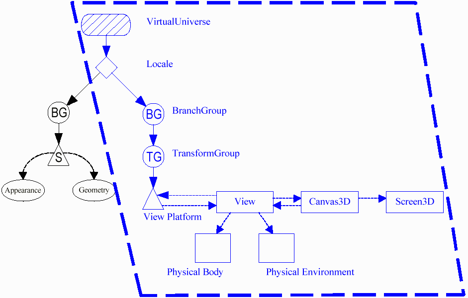
In other news I found a model of a puma. It was initally in autocad format but I exported it to 3d studio and then from that I used another program to convert it to VRML so you could look at it here. If it displays as a text file I'm not sure what's wrong. My tags are just like those on other pages with VRML, but it it displaying mine as text and theirs as VRML. I don't claim to get it. Maybe some content type tag would help, I dunno.
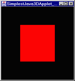
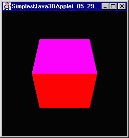
Thursday, June 10, 1999

I have a solution to the fact that this thing is way too huge, I will just continue it on another page. So if you want to continue, go there.
Go Home